High Dynamic Range (HDR) Photography
High Dynamic Range is a popular photographic technique that is used to produce more realistic photographic results or artistic images. It is a technique that can be used to try and replicate what the human eye can see as the dynamic range of a camera is limited and it is unable to record the lightest and darkest elements in a single photograph. This can be remedied by taking a number of photographs with varying shutter speed/aperture combinations and combining them using specialist software to produce a photograph with a greater dynamic range than can be recorded in a single photograph.
Many new digital cameras have the ability to produce HDR photographs using Auto Exposure Bracketing (AEB), special HDR settings (this may process the images for you resulting in an HDR photo on the camera but losing the originals) or manually setting the camera up.
Limitations of archaeological and cultural heritage photography
An intrinsic problem with taking photographs in archaeological and cultural heritage contexts is lighting; both too much and too little lighting are factors that hamper recording images that include as much detail as possible.
In the case of archaeological excavations attempts have been made to limit the problems in section photography by either reflecting more light in using white card or using a tarpaulin to cast a shadow. Both of these techniques work but require time and manpower.
The same problem is encountered in building recording where in an outside environment strong lighting can cause both bleached out areas and heavy shadows.

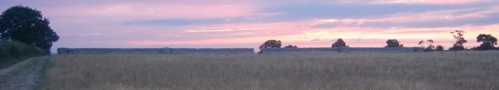
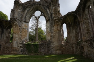
Netley Abbey, Hampshire – East Window. Photograph demonstrating the problem of strong oblique lighting causing both too much and too little light in the same image.
While lighting through windows can cause similar problems on the inside of buildings.

Netley Abbey, Hampshire – Sacristy/Library. Photograph demonstrating the effect of excessive light coming through a window causing the dual problems of both too much light near to the window and too little light in other areas.
In order to reveal elements in dark shadow a high exposure camera setting is required, while bright bleached out areas are only revealed with low exposures. These elements together with well lit areas cannot by revealed in one single photograph, this is where High Dynamic Range photography comes in.
HDR Photography in Archaeology
HDR Photography was introduced to Archaeology by David Wheatley in 2010, he provided examples of its use in improving the standard recording methods of excavations, cave sites and even using archived analogue archaeological photographs. Sadly its use was not embraced by the community probably due to technological limitations at the time and the inherent conservatism of the industry and museum archives which were yet to embrace digital photographic technology. Technology and the industry have now caught up with his ideas, with digital cameras being present on most if not all excavations, while other scholars have now begun to bring the technology to the technique of 3D recording using photogrammetry.
-

-
The interior of one of the rock-cut tombs at the necropolis of Cala Morel (Menorca) (Wheatley 2010)
-

-
Test pit recorded during investigations at Itchen Abbas, Hampshire (Wheatley 2010)
HDR Field Archaeology Photography
Photography is one of the primary recording techniques within field archaeology and has been since the introduction of discipline, but conservatism within field archaeology has meant that it was only fairly recently that digital photography became the primary recording technology.
Digital cameras have a number of benefits within archaeology:
- The ability to take numerous photographs on one memory card.
- No need to pay to process films.
- No need to digitize the photographs.
- Where once excavators may have been told to limit the number of photographs taken on an excavation to keep the processing costs down, digital media allows almost limitless photographs to be taken.
- Photographs can be as easy as point and click with the camera controlling all of the settings.
But they also have drawbacks:
- Where once archaeologists knew how to use an analogue camera to take bracketed shots, the automatic setting on digital cameras is commonly the only setting used as it produces results at a required level of quality, this means that the archaeologist may not know how to properly operate the camera.
- Although almost limitless photographs can be taken, limits should be included as the archive may still need to be sorted through.
- The requirements for digital storage can be complicated and costly.
Although not ideal, a number of modern cameras now come with an HDR setting on them which in many cases can be changed to the required level of bracketing, although only the merged photograph is saved losing the possibility of later re-processing the photographs with different settings.
Field Archaeology Archive Photographs
One benefit of traditional bracketing of analogue photographs for archaeological excavations is that they provide an ideal resource for conducting HDR processing. These archives have multiple photographs at different exposure levels which can be digitized and processed to provide better results than the originals and be re-entered into the archive with the digitized originals.
HDR using archive slides from excavations at the Cove, Avebury (Wheatley 2010)
HDR Building Photography
Building recording is an area that can be significantly enhanced by the use of HDR. It is difficult to provide adequate lighting in many cases, meaning that some areas are brightly illuminated while others are dimly lit loosing information in both cases.
Processing bracketed images into an HDR image provides a greatly enhanced image.
-
-
Netley Abbey, Hampshire. East Window comparison – Standard Photograph
-

-
Netley Abbey, Hampshire – East window comparison – HDR Photograph
HDR Photogrammetry
Recent developments in camera technology, HDR software and photogrammetry software have allowed the introduction of HDR Photogrammetry. Thanks to the additional information present in the photographs models of higher detail and accuracy can be created in non-optimal lighting conditions.
As well as the ability to use tone mapped images produced from HDR images the Agisoft PhotoScan Photogrammetry software can also process .exr file format High Dynamic Range images into 3D models.
HDR Object Photogrammetry
One area under study is its use in photographing objects. The benefits are determined by the type of material used, some are greatly enhanced by HDR while others are little altered.

Image matching result from the images originated
with different HDR processing: a) No HDR; b) tone mapped
images from HDR processing (Guidi et al 2014)
HDR Building Photogrammetry
We have already seen the benefits of HDR Photography in building recording and this can continue with photogrammetry.

Photogrammetry point cloud of the east window of Netley Abbey, Hampshire showing how the raking sunlight on the left-hand side of the window has bleached out the photographs and lost detail
Both the increased level of quality of the photograph and the higher amount of detail present in the 3D model can easily be seen in the HDR photogrammetry model.
-

-
Standard Photogrammetry using standard .jpg photographs
-

-
HDR Photogrammetry using processed .exr files
Software Solutions
A number of software solutions are available for the processing of HDR photographs, these range from high end photographic software such as Adobe Photoshop and Lightroom, through to HDR specific pieces of software and even open source solutions. HDRSoft’s Photomatrix comes in a number of versions which include plugins for different software packages such as Adobe Lightroom, Photoshop Elements, Photoshop and Apple Aperture. With low cost solutions such as Fusion HDR or free open-source solutions such as LuminanceHDR also being available.
In order to be view-able on low contrast monitors and paper the images need to go through a process called tone mapping, this replicates the appearance of the high dynamic range photograph on these media.
Downloaded imaged can be batch processed in software such as Photomatrix setting up how many images need to be merged together with a number of preset or custom settings allowing the images to be processed exactly as required. These pieces of software can also compensate for slight movement between the recording of the multiple images. The resulting images can then be saved as either .hdr (Radiance) or .exr (OpenEXR) file formats which record the HDR information.
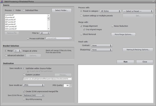
Batch processing of images within Photomatrix
Benefits
HDR photography can record more information in both photographs and photogrammetry models. By using open Source HDR software it can be free. Many cameras allow multiple bracketed photographs to be be taken automatically only adding a few seconds to the recording process.
It is also possible in some of the software to open a folder full of images and have the software batch process it without any user intervention once the preset settings have been loaded.
Drawbacks
Among the drawbacks are the fact that as the camera is taking multiple photographs it is difficult to stabilize the camera by hand, otherwise there will be movement between the photographs. Although movement between photographs can be corrected if you are bracketing shots and using software the automatic HDR setting on the camera will probably result in a blurry image.
UAV HDR Photogrammetry
UAV HDR Photogrammetry is an area I will be studying in the future. It has great potential for recording but will require a careful balance of UAV hovering, a steady gimbal, fast shutter speed and an adequate depth of field. It will be discussed in a future blog.
Sources
Guidi, G., S. Gonizzi, and L. L. Micoli. “Image pre-processing for optimizing automated photogrammetry performances.” ISPRS Annals of The Photogrammetry, Remote Sensing and Spatial Information Sciences 2.5 (2014): 145-152.
Kontogianni, G., and A. Georgopoulos. “Investigating the effect of HDR images for the 3D documentation of cultural heritage.” World Cultural Heritage Conference 2014 – Euromed 2014 – International Conference on Cultural Heritage Documentation, Preservation and Protection. (2014)
Ntregkaa, A., A. Georgopoulosa, and M. Santana Quinterob. “Photogrammetric Exploitation of HDR Images for Cultural Heritage Documentation.” ISPRS Annals of the Photogrammetry, Remote Sensing and Spatial Information Sciences 5 (2013): W1.
Wheatley, D. “High dynamic range imaging for archaeological recording.” Journal of Archaeological Method and Theory 18, no. 3 (2011): 256-271.