The recording of buildings is an important area in Cultural Heritage, whether for conditional surveys or to record something that is about to be destroyed.
Traditional methods rely upon survey equipment such as Total Stations to take a number of points on the façade, but this results in only points and lines with no great surface detail.
Other more detailed survey techniques such as laser scanning and photogrammetry have also been employed. But laser scanning is expensive and both the techniques are generally ground based missing detail of the façade that is not visible from this position. Scaffolding or a cherry picker can be used to record the whole of the building but again this can add to the cost the recording.
Photogrammetry is a low cost method of producing high quality results but relies upon having the camera parallel to the building to produce the best results, as capturing photographs from an angle brings inaccuracies into the recording as well as there being more detail at the bottom of the 3D model created than at the top.
The UAV would seem to provide an ideal platform to carry a camera parallel to the building, recording photographs with the required photogrammetry overlap. And with its autopilot it would seem possible to automate the recording process allowing the mapping of the façade in the same way that the UAV can map the ground.
There are of course a number of problems that need to be overcome.
Building Façade Recording
Manual
Building façade recording can be done manually with a UAV, but the larger and more complicated the building façade the mode difficult it is to do this accurately. As the pilot needs to control the UAV accurately in 3 dimensions as well as controlling its speed.
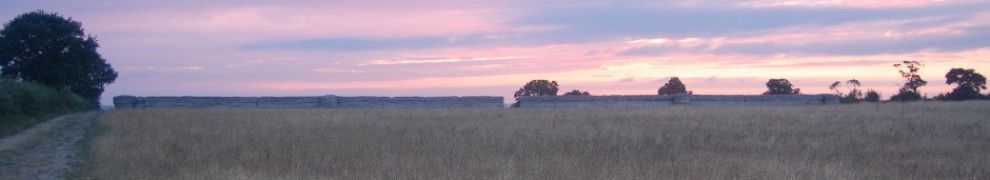
Although the results for an experimental UAV mission are acceptable the difficulty of maintaining a manual position can be seen in the image below.
-

- Bedham Mission Church – UAV Photogrammetry Model
-
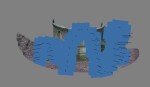
- Bedham Mission Church – UAV Camera Recording Positions
Automatic
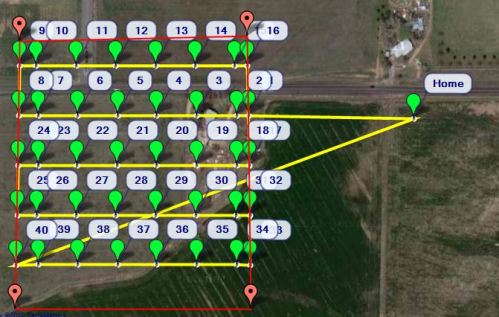
In order to automate the process you need to determine what parameters are required to record a building façade using photogrammetry.
These can be seen below.

Building facade recording parameters
First experimentation was done by taking the co-ordinates of the two ends of an example the wall from Google Earth (The south facing wall of the lay brothers’ quarters at Waverley Abbey in Surrey was used). These co-ordinates can then be used to determine the bearing that the wall lies upon and its width. Using the camera parameters and level of detail the required distance from the wall for the flight can be calculated using trigonometry. Trigonometry is once again used to calculate the offset positions for the left and right extent of the flight.

-
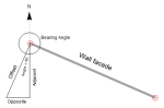
- Trigonometry used for calculations
The image overlap can be used to determine the number of photographs required in the horizontal and vertical, and hence the change of altitude that is required for each flight pass of the building.

Calculate altitude
Although it is planned to have the ability for the UAV to hover and take photographs, it is much easier to have it take photographs as it flies across the building façade. This requires the additional calculations and control of optimum flight speed and shutter speed to take photographs which are not adversely effected by motion blur.

Shutter speed formula

Shutter speed calculations
These preliminary calculations were done in Microsoft Excel.
DroneKit
The drone manufacturer 3DR provides a series of software development kits (SDKs) for writing applications to control your UAV using one of the open-source autopilot systems they support.
DroneKit Python uses the Python programming language and provides a number of examples to help with programming the flight of a UAV; these include flying from co-ordinate to co-ordinate up to complete missions. Together with this there is an API (application program interface) reference which provides all of the Python commands that can be used to control the UAV.
Python
Python is a fairly easy to learn programming language and as DroneKit already requires it to be installed and setup it makes sense to use the same language to calcuate the required paramaters for the flight path. This was done with the aid of a number of online resources. A graphical user interface (GUI) was created using the Tkinter Python package and was used to enter the data. The python code did the calculations then a file is exported which combines these calculations with the DroneKit code for controlling the autopilot. The final file when run will control the UAV flight.

Python GUI
Virtual Drone
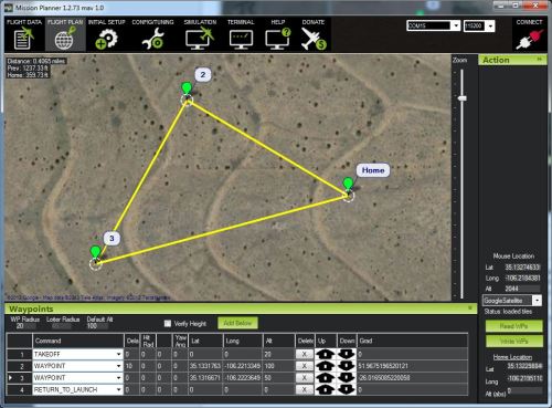
Experimentation doesn’t need to be done with a live UAV, it can actually be done with a virtual one using a number of pieces of open-source software. These include Mission Planner, ArduCopter, MAVProxy and SITL (Software in the loop)

Virtual Drone
Next Steps
Experimentation with a UAV using the hardware and software is the next step to test whether a GPS can be used in close proximity to a structure.
Limitations of standard UAV GPS accuracy to within the range of meters also complicates the use of this method of controlling the flight. This either needs to be solved with the use of a more accurate GPS (although the proximity to the building may block the signal), sensors that measure distances or the use of computer vision technologies to control the UAV position. The UAV afterall currently only need to fly between two set points then at set altitudes above the ground.